HC10DTP Quick Setup Guide
WARNING: Before powering up the robot, ensure you have completed the online training course available here.
NOTE: If you have not previously registered for online training, follow these instructions to create an account.
1. Unboxing
2. Mounting
3. Connecting the robot cables
4. Connecting the pendant
5. Connecting the AC IN cables
Unboxing
CAUTION: Take care when unpacking your HC10DTP robot and the Micro Controller. Use proper lifting techniques and/or equipment to protect against personnel or equipment damage.
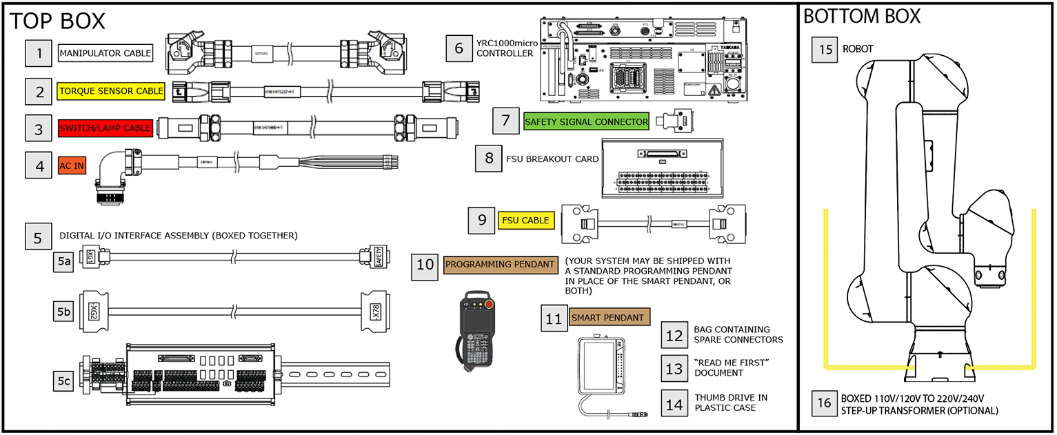
Below is a diagram of included components with corresponding numbers that appear on packaging or tags attached to the components. You may have purchased the Smart Pendant (shown) or a Standard Programming Pendant.
What's In the Box
Components are numbered for easy identification. Do not remove the packaging until you are ready to install each component. Please take a few minutes to identify each of the components and ensure that you have everything pictured.

Unboxing Methods
The largest item in the shipment is the HC10DTP robot. It weighs approximately 105lbs. Team lift the robot using OSHA safety guidelines, or use a crane or other lifting equipment to lift and position the robot. Lift instructions for using a crane can be found in Section 2.1.1 (Pages 2-1 and 2-2) of the HC10DTP Instructions manual (HW2480392).
Mounting
Once the robot has been removed from the crate and placed into position, it is important to properly mount it to a secure base. Make sure to use appropriate hardware. The baseplate should be rugged and durable to prevent shifting of the manipulator or the mounting fixture. A baseplate at least 32 mm or thick and anchor bolts M12 or larger are recommended.
Review the figure below below for additional details.

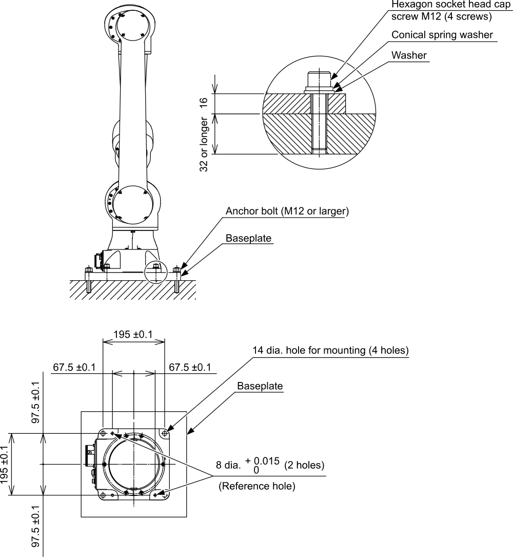
More detailed information on installation options may be found in the HC10DTP Instructions Manual (HW2480392).
Connecting the Robot Cables
Once your robot is securely anchored to an appropriate base, the next step is to connect the robot cables. Most of the cables are color coded to assist in making proper connections.
There are three robot cables:
|
Cable
|
Cable Description
|
|
1
|
1BC Manipulator cable (white labels)
|
|
2
|
Torque Sensor cable (yellow labels)
|
|
3
|
Switch/Lamp cable (red labels)
|
CAUTION: Do not remove or connect the 1BC, TQ and SW connectors while the power supply of the YRC1000/YRC1000micro is turned ON. Failure to observe this instruction may result in damage to the sensor.
Start connecting cables on the robot side. This way you can unroll the cables and route them more easily than if the cables are tangled or twisted together. There are three connectors on the base of the robot: Manipulator (1BC), Switch/Lamp (SW) and Torque Sensor (TQ).

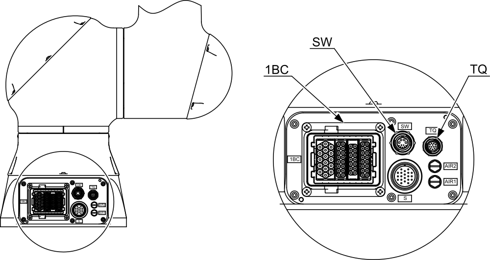
Remove shipping covers from the connectors. Insert the 1BC manipulator cable (1) into the 1BC connector (color coded white), then tighten the lever by hand until snug. If the connecter lever will not close, check to ensure the connector is fully seated and try again. Once connected and locked, lay the cable across the floor toward the controller. If you need to remove the 1BC manipulator cable, there is a small safety catch at the end of the lever. Depress the catch to release the lever.

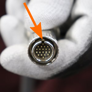
The next two cables, (2) and (3), have male and female ends. The female ends of the cables (no pins) attach to the robot. To connect the cables to the robot base, gently insert until the connector is fully seated and then turn the collar on the connector the direction indicated by the arrow to secure it.
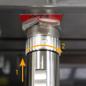
The connectors are keyed so that they only fit when properly aligned. If you cannot insert the connector, rotate it slowly until the guide pin and slot align and the connector seats.
The cable for the switch/lamp (3) connects to the SW port and is color coded red with a black stripe. The cable for the torque sensor (2) connects to the TQ port and is color coded yellow with a black stripe. Lay the SW and TQ cables next to the encoder/power cable, toward the controller, taking care not to twist or tangle the cables.

After all cables are properly connected on the robot side, make the connections to the YRC1000micro controller (refer to the controller panel diagram below). The manipulator cable (1) connects to the rectangular -X1 port (color coded white), similar to the 1BC connector in the previous step. Make sure the connector is firmly seated and the tighten the lever to lock the connector.
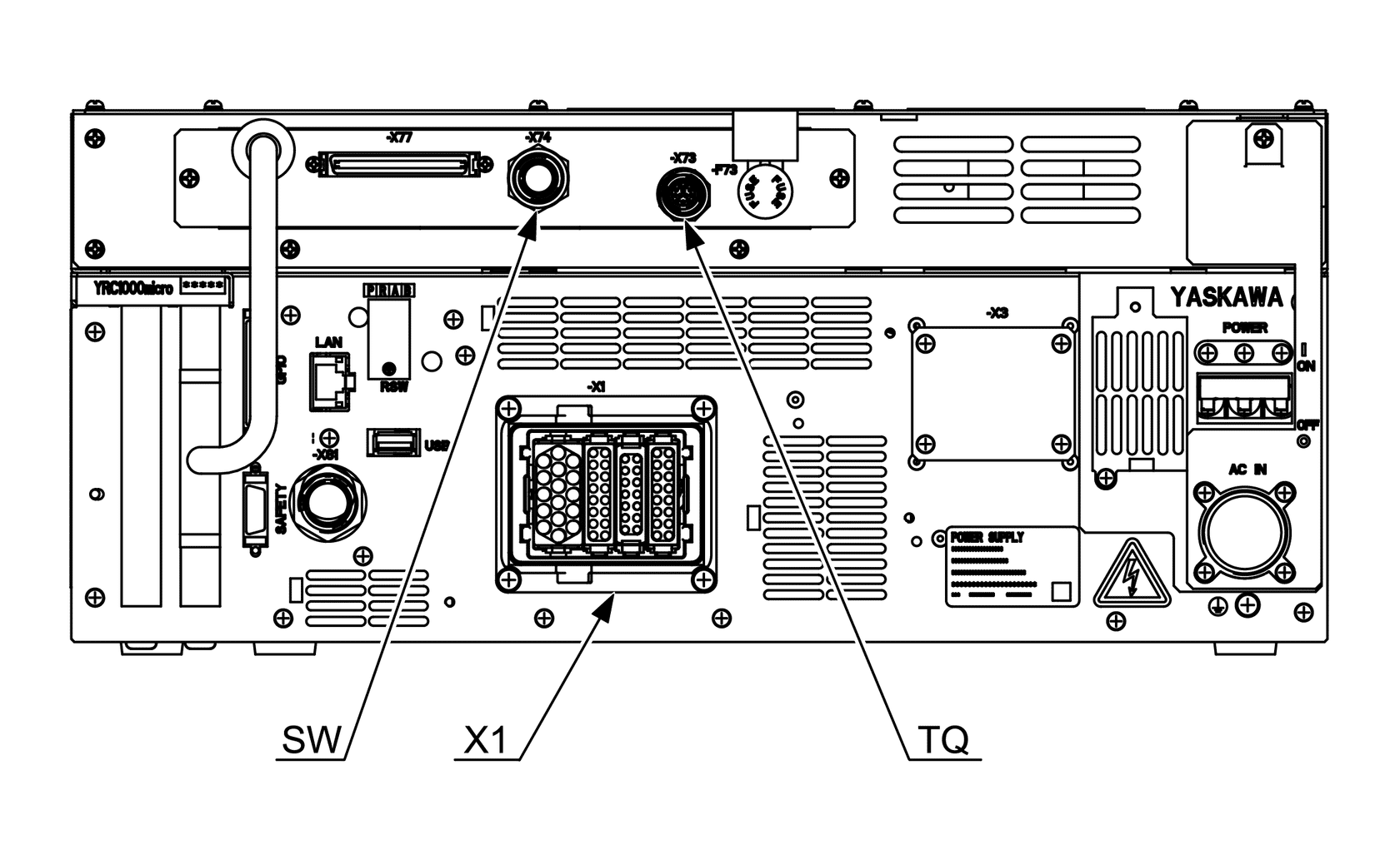
Connect the Torque Sensor cable (2) to the -X73 connector on the controller (color coded yellow). Line up the alignment marks and insert gently until you hear the connector click.
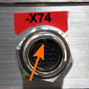
Connect the Signal/Lamp cable (3) to the -X74 connector on the controller (color coded red). Line up the alignment marks and insert gently until you hear the connector click.
This completes, the robot-controller connections. This is a good time to straighten up the cables and route them in a way to prevent tripping hazards or damage to the cables. Disconnect and reconnect the cables to reroute them as necessary.
Connecting the Pendant
Locate the Smart Pendant cable (10 or 11). It may already be attached to the pendant. Connect the pendant cable to the -X81 connector on the controller (color coded silver). Line up the alignment marks on the connectors and gently push until you hear a click.
Connecting the AC IN Cable

Assembled Power Connector Being Connected
After the robot and controller are properly connected, it is time to connect your power supply. All power connections should be made by a qualified electrician. Note that one end of the power cable has unfinished leads for flexibility in connecting to your power supply.
NOTICE: Spare connectors are provided in the accessory kit for you to fabricate your own cable if the supplied cable is not long enough. Refer to the table below for proper electrical wiring.
|
Pin No.
|
Signal Name
|
Description
|
|
A
|
L1
|
AC input (L1/R-phase)
|
|
B
|
N.C.
|
Not available
|
|
C
|
L3
|
AC input (L3/T-phase)
|
|
D
|
P.E.
|
Protective grounding
|
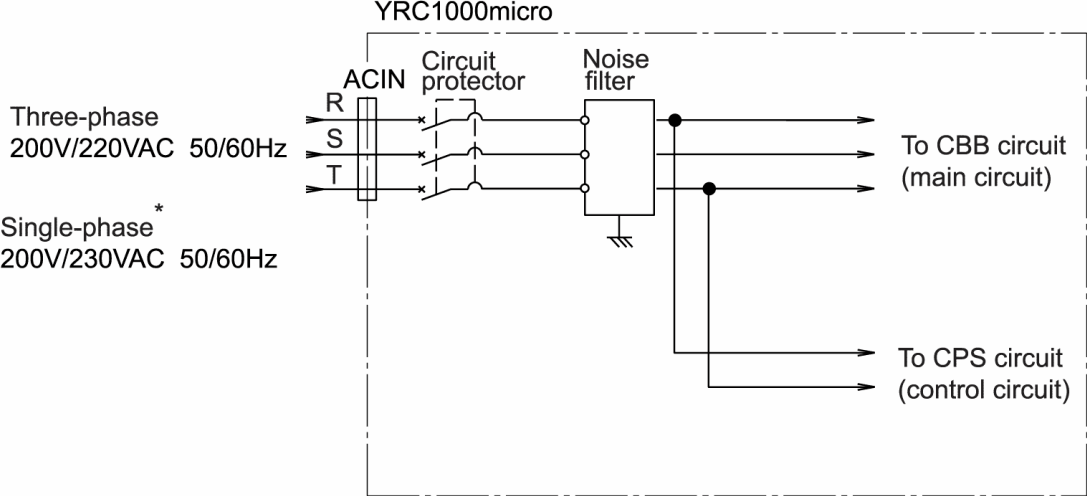
The schematic diagram below shows the proper power configuration. Single phase connects to R and T. If your power source is 110 VAC, you must supply a 1kVA step-up transformer to supply 220VAC Single-phase to the YRC1000micro controller.

Once the supply end of the AC IN cable (4) has been properly constructed and connected to the main power, connect the power cable to the AC IN connector on the controller (color coded orange). This cable is keyed so that it only fits when the contact pins are properly aligned. Rotate the connector slightly if it does not insert. Then tighten the collar on the connector to secure it.
Congratulations!
This completes the basic HC10DTP setup. There are additional components that must be connected before your robot can be operated, however, you must review the training before powering on or operating the robot to prevent damaging the robot. Training for the Standard Pendant is taught by a live instructor and must be completed in-person. Training for the Smart Pendant can be completed online. Please register to take the online course here.